close
Choose Your Site
Global
Social Media
Mismatched furnace insulation directly causes excessive fuel consumption, prolonged cycle times, and premature structural failure in high-temperature environments. Plant operators constantly face the tension between thermal mass and structural durability. You must balance the need for rapid heating and cooling against the strict requirements for mechanical stability and abrasion resistance on the hot face. Two primary refractory materials dominate this space: Insulating Fire Brick (IFB) and Ceramic Fiber Blanket. The optimal choice depends entirely on your specific firing cycles, furnace design, and atmospheric conditions. A poor selection leads to collapsed arches, eroded linings, and wasted energy. Understanding the technical differences between these materials ensures maximum operational efficiency and prevents catastrophic refractory failure during production runs.
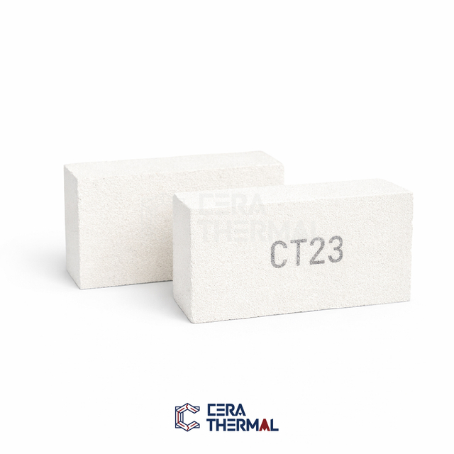
Cycle Dependency: Ceramic fiber blankets store up to 90% less heat than IFB of equivalent thickness, making them strictly superior for intermittent, fast-cycle firing.
Structural Integrity: Insulating fire brick provides necessary mechanical support and abrasion resistance that fragile ceramic fibers cannot offer, making IFB mandatory for load-bearing hot faces or high-velocity atmospheres.
Thermal Shock: Ceramic fiber is virtually immune to thermal shock, whereas IFB requires controlled heating and cooling curves to prevent spalling and cracking.
The Composite Approach: The most efficient industrial furnace designs frequently utilize both materials in tandem—using IFB for structural hot faces and ceramic fiber blankets for backup insulation.
Table of Contents
Selecting the correct refractory lining requires a rigorous evaluation of the operating environment. Peak temperature ratings represent only the baseline metric. You must analyze chemical exposure, gas velocity, and thermal cycling to determine material viability. Alkaline environments aggressively attack standard alumina-silicate materials, causing them to flux and melt well below their rated temperatures. Reducing atmospheres strip oxygen from certain refractory compounds, causing severe structural degradation over time. High-velocity gas streams easily erode low-density materials, dictating the need for dense, hard-faced surfaces in areas near burner blocks or exhaust flues.
Material grades dictate performance limits in the field. Insulating fire bricks utilize a standardized K-series classification system. Grades like K23, K26, and K28 correspond directly to their maximum temperature ratings (2300°F, 2600°F, and 2800°F). As the temperature rating increases, the brick generally becomes denser and more thermally conductive, sacrificing some insulation value for heat resistance. Ceramic fiber blankets also offer distinct classifications based on their chemical composition. Standard alumina-silicate fibers handle general applications up to 2300°F, while high-temperature zirconia-blended fibers resist shrinkage in extreme environments exceeding 2600°F. Matching the specific material grade to the thermal profile prevents premature material failure and costly downtime.
Firing cycles fundamentally alter insulation requirements. Continuous kilns operate for weeks or months without shutting down. These applications benefit heavily from high heat storage. The thermal mass of the refractory lining stabilizes internal temperatures, buffering against minor burner fluctuations and load changes. Intermittent kilns, however, heat up and cool down daily or weekly. These cyclic operations require low heat storage. Heavy thermal mass in an intermittent kiln wastes massive amounts of fuel, as the burners must heat the brickwork before heating the product.
Mechanical wear dictates structural requirements. Furnaces subjected to heavy vibration, physical impact, or abrasive particulate flow demand rigid support. Load-bearing walls, self-supporting arches, and hearth floors require high compressive strength. You must establish the baseline requirements for structural support before selecting an insulation strategy. Ignoring mechanical loads leads to catastrophic collapse, regardless of a material's thermal efficiency.
To properly evaluate a furnace for refractory selection, follow these field assessment steps:
Record the absolute peak operating temperature and add a 200°F safety margin to determine the required material grade.
Log the firing cycle duration from cold start to peak temperature, and from peak temperature back to ambient.
Identify the chemical composition of the furnace atmosphere, specifically looking for reducing gases, alkalis, or heavy metals.
Measure the gas velocity at the burner impingement zones and exhaust flues.
Assess the mechanical load requirements, including the weight of the product on the hearth and any vibration from adjacent heavy machinery.
Insulating fire brick provides a reliable balance between thermal resistance and structural integrity. Manufacturers produce IFB by mixing refractory clays with combustible materials like sawdust, petroleum coke, or specialized organic fillers. During the firing process in the manufacturing plant, these additives burn out, leaving a highly porous structure behind. This porosity traps dead air, which acts as the primary insulating mechanism. The resulting brick is significantly lighter than dense firebrick but retains enough structural rigidity to build self-supporting walls and complex roof geometries.
Thermal mass remains the defining characteristic of IFB. The solid matrix of the brick absorbs and retains substantial heat energy. In continuous production environments, this heat storage acts as a thermal flywheel. It maintains uniform temperatures across the furnace chamber, ensuring consistent product quality. The retained heat minimizes temperature drops when operators open furnace doors to load new batches or when cold air infiltrates the system. For steady-state operations, the initial energy required to heat the brickwork becomes negligible over a long production run, making the stability it provides highly advantageous.
Structural load-bearing capabilities separate IFB from fibrous insulators. IFB possesses measurable cold crushing strength, allowing operators to construct complex geometries without extensive steel support. You can build sprung arches, load-bearing hearths, and tall vertical walls. The rigid surface resists mechanical abrasion from moving parts, sliding loads, and high-velocity burner exhaust. This durability makes IFB the standard choice for the hot face in heavy industrial applications like rotary kilns, large heat-treating furnaces, and glass melting tanks.
Despite its strengths, IFB carries specific implementation risks that operators must manage. The rigid structure makes it highly susceptible to thermal shock. Rapid temperature changes cause uneven expansion and contraction across the brick's profile, leading to spalling, cracking, and eventual face loss. Operators must strictly control heating and cooling curves to protect the lining. Installation also requires skilled masonry labor. Bricklayers must cut blocks with wet saws, mix high-temperature refractory mortar to the correct consistency, and ensure precise joint alignment. Furthermore, the high thermal mass incurs a severe energy penalty during the heat-up phase of intermittent operations, as the burners fight to saturate the brick before the furnace reaches its set point.
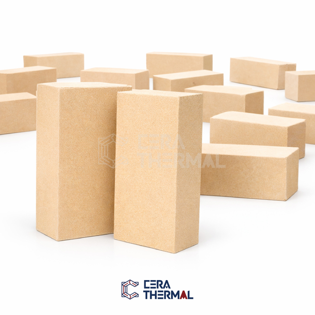
Ceramic fiber blanket changes the baseline for furnace efficiency in cyclic operations. Manufacturers create this material by melting high-purity alumina and silica in an electric arc furnace, then spinning or blowing the molten liquid into fine fibers. These fibers are needled together mechanically to form a flexible, lightweight blanket without the use of organic binders. The resulting structure consists mostly of trapped air. This extreme porosity gives the blanket exceptional insulating properties with a fraction of the weight of traditional brick.
Low heat storage drives the efficiency of ceramic fiber. The low density means the material absorbs almost no thermal energy. Furnaces lined with fiber reach operating temperatures rapidly. Burners expend energy heating the product rather than the furnace walls. Upon shutdown, the furnace cools quickly, allowing operators to unload products and initiate the next cycle faster. This rapid cycling drastically cuts fuel consumption and increases overall production throughput in intermittent operations like shuttle kilns, blacksmith forges, and batch heat-treating ovens.
Flexibility and thermal shock resistance provide major operational advantages on the shop floor. Ceramic fiber lacks the rigid bonds found in brick. The fibers move independently, allowing the material to absorb rapid thermal expansion without cracking. You can fire a fiber-lined furnace at maximum burner output immediately, completely ignoring the slow heat-up curves required for IFB. The flexible nature also allows installers to wrap complex geometries, line irregular steel shells, and compress the material into tight joints to prevent heat leaks.
High-temperature applications require specialized fiber variants to prevent catastrophic failure. Standard spun fibers begin to shrink and devitrify at sustained high temperatures, turning into a brittle, crystalline structure. For inner layers exposed to extreme kiln environments, operators must use Zirconia-stabilized ceramic fiber. The addition of zirconia raises the continuous use limit and prevents excessive shrinkage. Shrinkage remains a critical concern in fiber linings, as gaps between fiber modules allow extreme heat to bypass the insulation and reach the steel furnace shell, causing warping or structural failure.
Fragility represents the primary limitation of ceramic fiber. The material possesses zero load-bearing capacity. You cannot build a self-supporting structure with a blanket; it requires extensive steel anchoring systems or adhesive bonding to a rigid shell. The soft surface degrades rapidly under mechanical impact or abrasion. High-velocity gas streams easily strip fibers from the hot face, causing severe erosion and contaminating the furnace atmosphere with airborne particulates. Operators must limit gas velocities or apply protective surface coatings to prevent rapid degradation in turbulent environments.
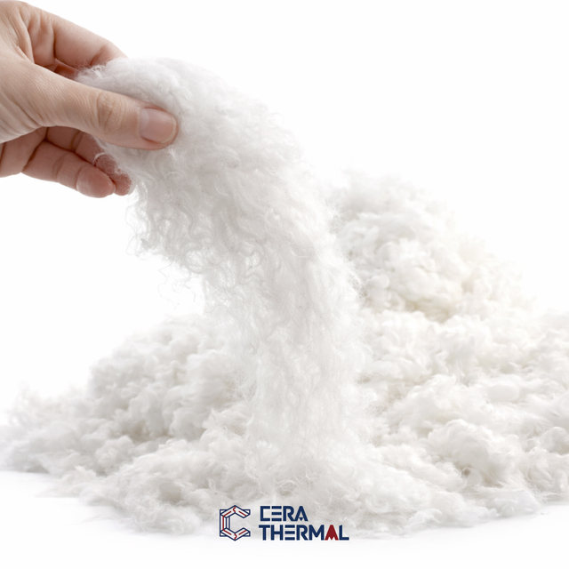
When evaluating insulating fire brick vs ceramic fiber blanket, operators must analyze energy efficiency, installation logistics, and long-term durability. The thermal conductivity of ceramic fiber is generally lower than IFB at equivalent temperatures, meaning it blocks heat transfer more effectively per inch of thickness. However, the true differentiator lies in heat storage. Ceramic fiber stores approximately 90% less heat than IFB. In a daily cycling kiln, replacing brick with fiber often reduces fuel consumption by 30% to 50%. Conversely, in a continuous tunnel kiln, the steady-state efficiency of IFB proves superior due to its thermal stability and resistance to wear over multi-year campaigns.
Installation complexity heavily influences project timelines and labor budgets. IFB installation demands specialized masonry skills. Workers must mix high-temperature mortar, cut bricks with wet saws, and carefully stagger joints to prevent heat tracking. The mortar requires specific curing times and controlled dry-out schedules before the furnace can operate at full capacity. Ceramic fiber deployment is significantly faster. Installers impale layers of blanket onto welded steel anchors, secure them with ceramic cuplocks, and compress the joints. Modular fiber blocks further accelerate installation, allowing rapid relining of large industrial vessels with minimal downtime.
Lifespan and maintenance requirements differ drastically between the two materials. IFB offers a longer mechanical lifespan in harsh environments. The hard surface withstands minor impacts, abrasive dust, and aggressive burner flames. Maintenance typically involves localized patching of mortar joints or replacing individual damaged bricks. Ceramic fiber degrades faster under mechanical stress. Shrinkage causes gaps to form between blankets, requiring operators to pack loose fiber into the voids to prevent shell damage. The hot face may require periodic spraying with rigidizers to combat velocity erosion. While fiber requires more frequent maintenance, the repairs are generally faster and less labor-intensive than masonry work.
Health, safety, and environmental compliance dictate specific handling protocols for both materials. Cutting IFB generates crystalline silica dust. Prolonged inhalation causes silicosis, a severe lung disease. Workers must use wet saws, localized exhaust ventilation, and N95 or P100 respirators during installation and demolition. Ceramic fiber presents different hazards. Refractory Ceramic Fibers (RCF) are classified as possible human carcinogens. Handling the blankets releases respirable airborne fibers that irritate the skin, eyes, and respiratory tract. Installers must wear full-body Tyvek suits, gloves, and high-efficiency particulate respirators. Proper disposal of spent RCF also requires adherence to strict environmental regulations, often requiring specialized landfill processing.
Refractory Material Performance Metrics
Performance Metric | Insulating Fire Brick (IFB) | Ceramic Fiber Blanket |
|---|---|---|
Thermal Mass & Heat Storage | High (Requires significant energy to heat) | Very Low (Heats and cools rapidly) |
Thermal Shock Resistance | Poor (Requires slow heating/cooling curves) | Excellent (Immune to rapid temperature changes) |
Compressive Strength | High (Capable of supporting structural loads) | Zero (Requires steel anchoring systems) |
Abrasion & Velocity Resistance | Good to Excellent (Withstands turbulent gas) | Poor (Susceptible to fiber erosion) |
Installation Speed | Slow (Requires skilled masonry and curing) | Fast (Pinning, layering, and folding) |
Primary Application | Continuous kilns, abrasive environments | Intermittent kilns, rapid cycling operations |
The debate over insulating fire brick vs ceramic fiber blanket often concludes with a hybrid approach. Industry-standard practice utilizes both materials to maximize efficiency and durability. Engineers design composite linings by placing a dense refractory or IFB on the hot face. This inner layer provides the necessary structural support, abrasion resistance, and protection against high-velocity gases. Behind this hard face, installers place multiple layers of ceramic fiber blanket. The fiber acts as backup insulation, drastically reducing the overall thermal conductivity of the wall without adding excessive weight or thermal mass to the furnace structure.
Layering strategies require precise thermal gradient calculations. The engineering team must ensure the interface temperature between the IFB and the ceramic fiber does not exceed the fiber's maximum continuous use rating. By adjusting the thickness of the IFB hot face, operators can control the temperature reaching the backup layers. This allows the use of lower-grade, less expensive standard ceramic fibers near the cold face, optimizing material costs without sacrificing performance. Proper vapor barriers must also be considered if the furnace atmosphere contains corrosive gases that could condense within the porous fiber layers.
Middle-ground alternatives bridge the gap between rigid brick and soft blanket. Ceramic fiber boards offer more structural rigidity than blankets while maintaining low thermal mass. Manufacturers vacuum-form these boards with organic and inorganic binders. They resist higher gas velocities and provide a flat, stable surface for furnace roofs and doors. Liquid rigidizers offer another transitional solution. Operators spray colloidal silica onto the hot face of a fiber blanket. The rigidizer penetrates the surface, curing into a hard crust that resists erosion and minor abrasion, extending the life of the fiber in turbulent environments.
This hybrid approach neutralizes the inherent weaknesses of both materials. The IFB hot face protects the fragile ceramic fiber from direct flame impingement, mechanical damage, and chemical attack. Simultaneously, the highly efficient fiber backup prevents the IFB from bleeding heat through the steel furnace shell. The composite system reduces the total weight of the lining compared to a solid brick wall, lowers the external skin temperature to safe working levels, and provides unmatched long-term operational stability for heavy industrial applications.
Neither insulating fire brick nor ceramic fiber blanket is universally superior. The optimal choice depends strictly on the thermal mass requirements of your firing cycle and the mechanical demands of your furnace environment. Continuous operations and abrasive environments demand the structural rigidity of brick. Intermittent operations and rapid thermal cycling require the lightweight efficiency of fiber. For heavy-duty industrial applications, a composite system utilizing both materials yields the highest performance.
With roots in Nanjing, China dating back to 2002, CERA THERMAL has developed from a high-temperature materials business into an integrated refractory and thermal insulation solution provider covering material R&D, manufacturing, processing, engineering applications, and international services. Its portfolio includes ceramic fiber products, insulating and refractory bricks, castables, mortars, and complete refractory lining solutions, supporting industries such as petrochemical, metallurgy, cement, glass, ceramics, power generation, and aluminum.
To optimize your furnace insulation, take the following actions:
Audit your current firing cycles to determine if your operation is continuous or intermittent.
Measure the gas velocity and mechanical abrasion levels present at the hot face of your furnace.
Calculate the potential fuel savings of switching to a low-mass fiber lining if you run daily heating and cooling cycles.
Consult with a qualified refractory engineer to design a composite lining system tailored to your specific peak temperatures.
A: Yes, but only for insulation in non-load-bearing applications. Ceramic fiber provides superior thermal resistance and faster cycling times. However, it lacks structural integrity. You cannot use it for hearth floors, self-supporting arches, or areas exposed to heavy abrasion and high-velocity gases.
A: Ceramic fiber blanket insulates better per inch of thickness. It possesses lower thermal conductivity and stores up to 90% less heat than IFB. This makes fiber significantly more efficient at blocking heat transfer and reducing fuel consumption in cyclic operations.
A: Ceramic fiber blanket stores roughly 90% less heat than an insulating fire brick of equivalent thickness. Its highly porous, low-density structure prevents heat absorption, allowing the energy to remain inside the furnace chamber rather than soaking into the refractory lining.
A: Direct flame exposure is safe only if gas velocities remain low. High-velocity burner flames will erode the fragile fibers. To prevent degradation and shrinkage at the hot face, operators should apply a liquid rigidizer, use ceramic fiber board, or install a protective IFB layer.
A: You attach ceramic fiber to existing brickwork using high-temperature refractory anchors. Installers drill into the brick, secure stainless steel or ceramic anchors, impale the blanket over the pins, and lock the layers in place using specialized ceramic cuplocks or buttons.
A: IFB generally offers a longer mechanical lifespan, often lasting many years in continuous operations due to its rigid structure. Ceramic fiber may require more frequent patching or replacement due to high-temperature shrinkage, mechanical damage, or velocity erosion in harsh environments.